Our final small design task in our MIE243 class was to design a gearbox which was 3D printed, coaxial, provide at least a 12:1 speed reduction, and have the ability to be assembled quickly.
The requirements for the gearbox are that it should have at least a 12:1 speed reduction and that the input and output should be collinear. There is motion modification in terms of a change in speed and torque, but it remains rotational continuous from input to output. The total print time of the entire design cannot exceed 6 hours, and the design needs to be self-supporting. We also decided that the gear train should be self-contained to both emulate the dissected gearbox and for safety reasons.
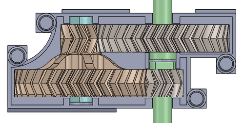
Our group decided to go with two herringbone gear pairs, each with a ratio of around 3.6:1. We chose herringbone gears due to their superior motion transmission qualities compared to spur gears, especially in terms of torque transmission from the continuous contact surface. There is no trade-off, as printing herringbone gears is not a difficult operation compared to spur gears. The larger gears have 36 teeth, and the smaller gears have ten teeth. To create a collinear design, there are three shafts, one for the input gear, one for the output, and one for motion support. The small input gear is paired with a larger gear to create a 3.6:1 speed reduction. This gear is physically connected to a 10-tooth gear to increase the strength of this torque transmission. There is a shaft to support the rotary motion, but this shaft does not transmit power. The 10-tooth herringbone gear is paired with the 36-tooth output gear to create another 3.6:1 speed reduction pair, giving a total of a 12.96:1 ratio. This meets the requirement of having at least a 12:1 speed reduction.

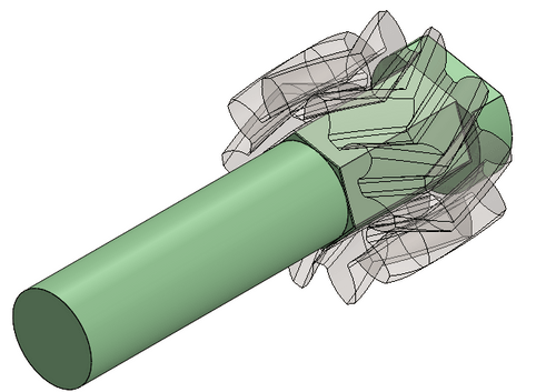
Attaching the shafts to the gears is a simple operation. For the part with two gears, the shaft is sized with a loose tolerance such that the gear can freely spring. This is because the shaft does not need to transmit motion. For the input and output shafts, the motion is transmitted from the shaft to the gear using a hexagonal profile, which runs along the width of the gear. The shafts are attached by pushing them from one side, as there is a cap on the shaft, which constrains shaft movement in one direction. Both ends of all shafts are supported by circular bushing areas printed on the housing. These support areas also constrict the movement of the gears along the shaft, which means that once the housing is assembled, all gears are fully constrained along the shafts but are still free to spin.

Since the housing supports the shafts, and by extension the gears and motion transmission, it is vital that the housing is able to attach together, and not come apart. To achieve this, we use a combination of locating pins, and cantilever clips. The pins help locate the part, and prevent any torsional forces. The clips then are to support lateral forces, coming from forces on the bushings, when the gears spin. We also decided to make the housing falls solid. This is for safety concerns, so that once the gearbox is assembled there is no chance of something, or someone getting jammed in the gearbox. It also prevents damage from failure, as if a gear is to break at high speed, the housing will be able to stop the projectile.
We also optimised our design for assembly. There are only seven simple operations needed to assemble our gearbox. As well, when the housing is assembled, which is a non-reversible operation, the locating pins ensure that there is only one correct way for the housing to be assembled. This means even from user error, the gearbox will not be irreversibly assembled incorrectly. The housing shape itself, with one side being square and the other being arced, allows for the user to easily discern the orientation of the parts, and where they should go, making assembly even easier.
There are, however, drawbacks to our design. Having the housing attached at the point where power is transmitted, such as in the bushings, means that the bushings are prone to forces, which could lead to the design failing. This could happen for example if the clips were to fail, as if they did, the housing would be free to separate, allowing for the design to fail. Another downfall of the design is the gear alignment. Since the housing bushings also constrain the gear movement along the shaft, there is possibility for the gears to wear on their ends, which would decrease performance of the system, and also eventually fail.