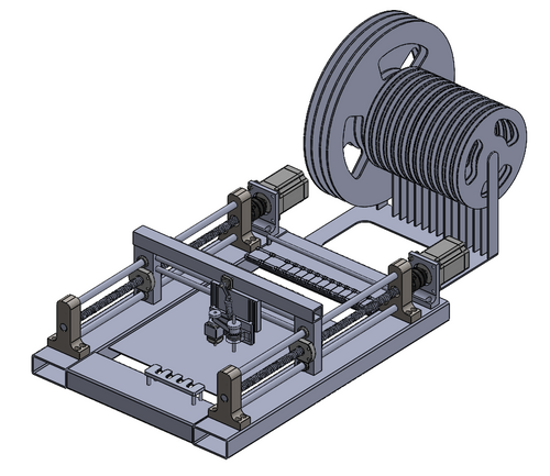
Our final project in our MIE243 class was to design a pick and place machine. This page outlines the design of this, from concept generation to final design.
Our team first determines the requirements for our design, after a series of researching other pick and place machines, and by incorporating requirements from our course.
From here, we took time to develop different candidate designs.
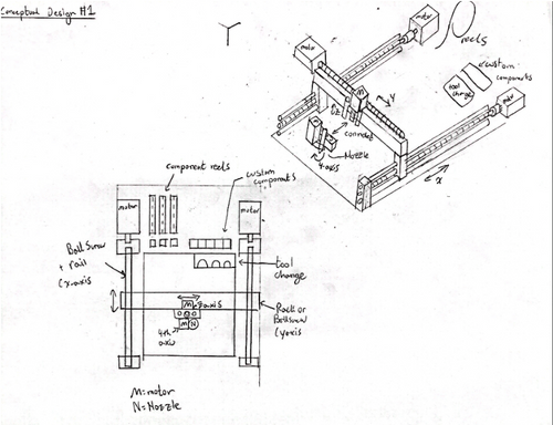
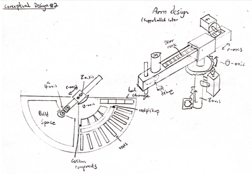
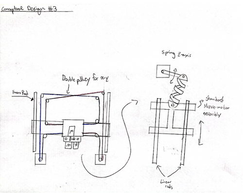
We chose design 1 due to its simplicity and proven record in general CNC design, and in pick and place machines.
To optimize our final design, the first step in our design process was to do a subsystem optimization. We limited our subsystems to each of the four axes (x, y, z, and nozzle), the system to grab components from reels, and the system to change the nozzles. Overall, our process was broken down as first determining the subsystems within each system and from there, using a weighted decision matrix to determine which specific systems should be used within each subsystem (such as for linear support or motion).
After this was performed, the different components and their relevant attributes (cost, weight, and so forth) were included in a spreadsheet. These parts were sourced from McMaster-Carr, and while the parts would undoubtedly be less expensive if sourced in bulk, the program’s cost metrics were used solely as a reference point for cost. After this was done, the parts were combined in their possible permutations, and the output of various calculated attributes (speed, accuracy, cost) were compared.
These attributes were scaled and weighted to find the optimal combination of components in the solution space. In some cases, we determined that this optimization was not required. For example, when researching reel rotation and indexing, it was discovered that additional motors are not required to turn the reels to indexed values as this process is instead left to a different process which does not require a subsystem and optimization to solve.
Alternatively, research on nozzle types (within the scope of ball-locking designs) did not require an optimizable subsystem since a universally standardized and easily attainable component already existed.
For the x-axis, we identified that our system would have three main components, the motion transmission, the motion support and the motor. After doing a review of the various systems, we selected different possible subsystems within our design. For motion transmission we consider rack and pinion, ball screw, leadscrew, belt and pulley and chain and sprocket. For motion transmission we consider linear shafts, support shafts, guide rails, track rollers and t-slot extrusion, each of which using their respective motion transmission component, such as a linear bearing. Lastly, for motion transmission we decided to use stepper motors as they are good for precision movement. For motion transmission and support, we determined various attributes that we cared about, according to our engineering specification, and ranked each system out of ten on these attributes. The tables below outline our ranking.
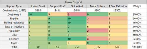

We chose to use a linear shaft ballscrew combination. From here, we looked at McMaster-Carr selection for components which were the size we wanted (~500mm), and created tables with the components relevant information.

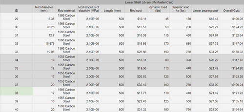
With this information, we created various relevant metrics which could be derived from combinations of components, such as max speed, linear force, overall cost, moment of inertia and step size. From these, we weighted the categories, and calculated values and scored for each permutation of linear motion, support and motor. The components with green highlights optimized the solution space relative to our weights. This optimization will not be shown due to its size.
This process was repeated for all optimizable subsystems.
From here, it was simply a matter of putting our specifications into CAD. Below is an isometric view of our current CAD.
